 Skip to content
Plannar Array & Discoidal Capacitors
Supporting fast delivery of full-size multilayer ceramic capacitors and offering a choice of 12 series, including low capacitance, medium and high voltage, shieldtechnic produces multi-layer ceramic capacitors capacitors that are small, lightweight, highly reliable and easy to assemble.
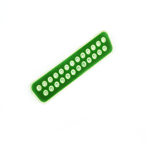
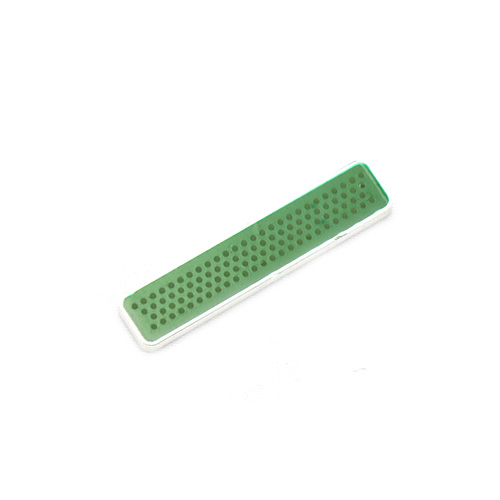
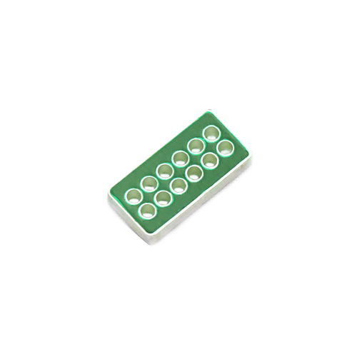
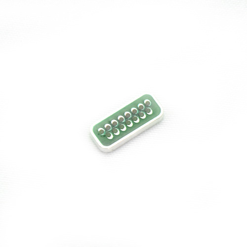
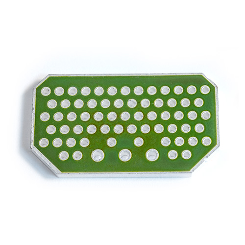
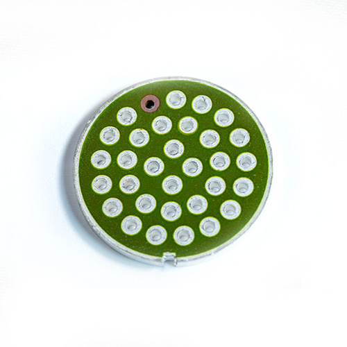
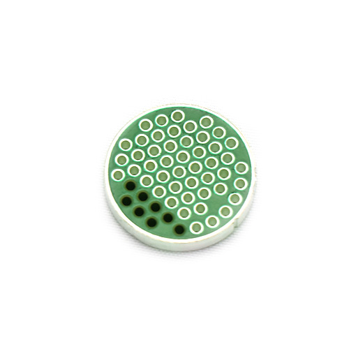
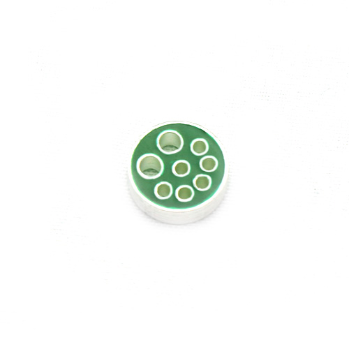
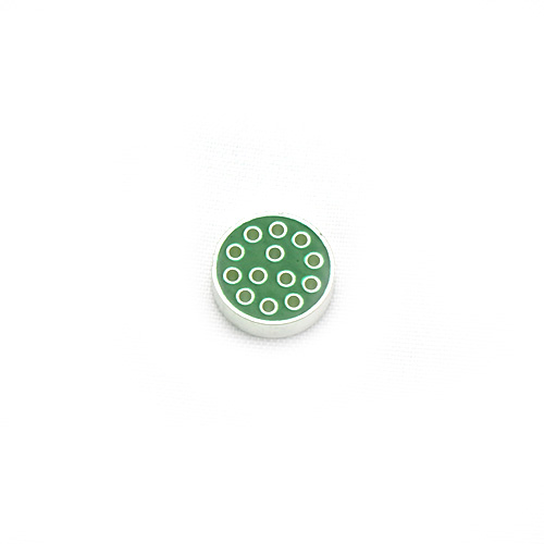
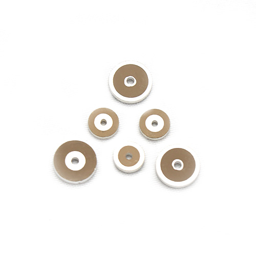
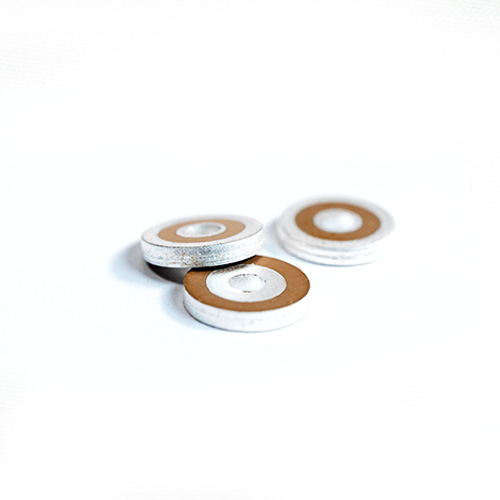
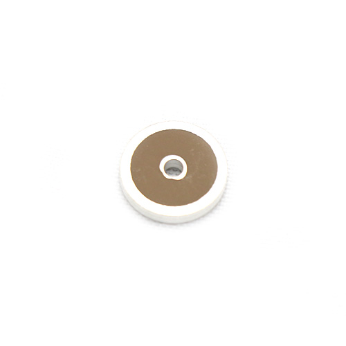
Some Plannar Array & Discoidal Capacitors We Previously Made
We have extensive experience in customizing plannar array & discoidal capacitors, some of which we have produced in recent years are listed below.
Let's Talk About Your Planar Array Capacitor Needs
No matter which style of multi-layer ceramic capacitors you need, no matter how special or complex the application, we have the professional team and rich experience to provide you with customized solutions. Simply tell us what you need and our technical experts will quickly provide you with detailed product literature, technical specifications and customized recommendations.
What is a Plannar Array & Discoidal Capacitor?
Planar array capacitor is a planar structure capacitor formed by alternately stacking multiple ceramic layers with metal electrodes. Each ceramic layer is printed with interleaved metal electrodes, and the electrodes of adjacent layers form positive and negative plates. The multilayer stacking achieves high capacitance and stable electrical performance.
Classification of planar array & discoidal capacitors
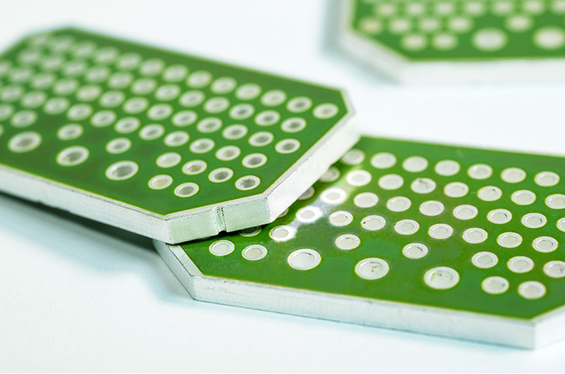
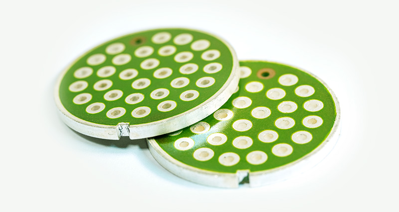
- Circular Arrays
- Rectangular Arrays
- D-Subminiature Rectangular Arrays
- Custom Capacitor Arrays
- Discoidal Capacitors
Advantages of Plannar Array & Discoidal Capacitor
The planar array capacitor has advantages such as a compact size that saves space, light weight, ease of assembly, high reliability, and strong shielding and isolation capabilities. It is particularly suitable for meeting the development requirements of filter electrical connectors in terms of high density, numerous cores, and interference resistance. It effectively realizes the functions of filtering, shielding, isolation, and resistance to conducted and radiated interference in filter electrical connectors, thereby enhancing the system’s capability to resist electromagnetic interference.
The Parameters of Plannar Array & Discoidal Capacitors
Capacitance
Range
The capacitance range of planar array capacitors is usually wide, depending on design requirements. For example, the capacitance values of certain arrays may range from a few picofarads (pF) to several hundred nanofarads (nF).
Accuracy
Capacitance accuracy is an indicator of the deviation between the actual value and the nominal value, usually expressed as a percentage.
Temperature Coefficient
The characteristic of capacitance variation with temperature, usually expressed in ppm/℃.
Size and Layout
Array Size
The physical dimensions of planar array capacitors, including length, width, and thickness.
Electrode Spacing
The spacing between electrodes affects the capacitance value and parasitic inductance.
Contact Spacing
The spacing between contacts in an array, usually measured in millimeters (mm), affects the ability of high-density layouts.
Electrical Performance
Equivalent Series Resistance (ESR)
The equivalent resistance of a capacitor under AC signals, which affects energy loss and efficiency.
Equivalent Series Inductance (ESL)
Parasitic inductance of capacitors that affects high-frequency performance.
Dissipation Factor (D)
An indicator of dielectric loss, usually expressed as a percentage or decimal.
Temperature Characteristic
Working Temperature Range
The temperature range within which the capacitor can work normally, usually expressed in ℃.
Temperature Stability
The stability of capacitance value with temperature changes, usually measured in ppm/℃.
Dielectric Material
Type
The dielectric material determines the stability, withstand voltage and temperature characteristics of the capacitor. Common dielectric materials include X7R, COG (NPO), etc.
Dielectric Constant
The dielectric constant of the material affects the capacitance value and its stability.
Rated Voltage
DC Voltage
The DC voltage that a capacitor can work normally for a long time, usually measured in volts (V).
AC Voltage
For AC applications, the rated voltage of capacitors needs to consider peak voltage and frequency.
Naming Rules for Our Company's Plannar Array Capacitors
The composition of our company’s planar array capacitor model specifications complies with the following regulations:
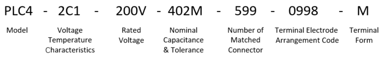
Model
Among the four characters in the model, the first and second characters "PL" represent planar array ceramic capacitors; The third character represents ceramic material, "T" represents Class 1 ceramic capacitor, and "C" represents Class 2 ceramic capacitor; The fourth character "4" represents a multi-layer structure.
Voltage Temperature Characteristics
For characteristics CH and 2C1, when the capacitor model starts with "PLC4," the temperature characteristic identifier "2C1" is omitted.
Rated voltage
The rated voltage is directly marked in volts (V).
Nominal Capacitance
The nominal capacitance is expressed in picofarads (pF) using three digits. The first two digits are significant figures, and the last digit indicates the number of zeros to follow. A letter appended after the capacitance indicates the tolerance code. When two or more capacitance are included, they should be listed in ascending order of nominal capacitance. For capacitors with the 2C1 characteristic, the number "0" is used to indicate no capacitance requirement for a specific hole. When the upper limit of capacitance for a single signal pole is more than twice the lower limit, the nominal capacitance is marked as the midpoint of the capacitance range. Example: "0501Z102M" indicates three capacitances, including no capacitance requirement, a nominal capacitance of 500pF with tolerance Z, and a nominal capacitance of 1000pF with tolerance M.
Tolerance of Nominal Capacitance
The allowable tolerance of nominal capacitance is represented by the letters specified in Table 1.
| Table 1 Allowable tolerance code for nominal capacitance | ||
| Number | Tolerance of nominal capacitance | Code |
| 1 | ±20% | M |
| 2 | -20%~+50% | S |
| 3 | -20%~+80% | Z |
| 4 | 0~+100% | H |
| 5 | / | Xa |
| When the upper limit of the capacitance of a single signal pole is more than twice the lower limit, the tolerance of the nominal capacitance is represented by the letter “X”. | ||
Standard Number of Matched Electrical Connector
The number following "Nominal Capacitance and Tolerance" in the model designation represents the national military standard number of the People's Republic of China adopted for the matching electrical connector.
Terminal Electrode Arrangement Code
The terminal electrode arrangement code is represented by the standard hole position arrangement parameters specified in the insulation mounting plate of the matching electrical connector.
Terminal Form
The composition of the metal material on the surface of the lead out terminal is shown in Table 2.
| Table 2 Lead out terminal form | |
| Code | Surface metal material of lead out terminal |
| (Omitted) | Platinum silver |
| M | Palladium silver |
Installation of Planar Array Capacitor
The assembly of planar array capacitors with the contacts and housing of filter electrical connectors is a critical process in the production of filter electrical connectors. Since planar array capacitors are ceramic capacitors, structural design and assembly processes of filter electrical connectors should avoid subjecting the capacitors to excessive stress. Our company recommends two methods for installing planar array capacitors.
Installation Method 1
The inner hole and outer ring of the planar array capacitor are connected to the contacts and housing through spring clips. The spring clips should be made of materials with good conductivity, elasticity, and resistance to elastic degradation over time to ensure that the capacitor maintains good electrical contact with the contacts and housing of the filter electrical connector during use.
Installation Method 2
The inner hole of the planar array capacitor is connected to the contacts by soldering, while the outer ring is connected to the housing through spring clips. Due to the significant difference in thermal expansion coefficients between the planar array capacitor and the contacts, low-stress solder should be used for soldering, and sufficient preheating is required during the process. Reflow soldering is recommended, with the maximum soldering temperature not exceeding 265°C and the duration at the highest temperature not exceeding 10 seconds. After soldering, the product should be cooled slowly. Once it has completely cooled to room temperature, residual flux should be cleaned with a solvent and dried.
Precautions for Planar Array Capacitors
- Handle planar array capacitors gently during use to avoid damage caused by collisions.
- Surface contamination of planar array capacitors can lead to reduced insulation performance, so it is advisable to wear rubber gloves when handling the product.
- During the assembly of filter electrical connectors, avoid contaminating the inner hole and outer ring of the capacitor with resin-based substances used in production. Otherwise, the capacitor’s electrodes may not be properly connected, affecting the performance of the filter connector.
Application Industries of Planar Array Capacitor
The application of planar array capacitors spans a wide range of industries, including but not limited to the following areas:
Consumer Electronics Industry
Touch Screen Technology
Plannar array capacitive sensors are widely used in the touch screen of smart phones, tablet PCs, car navigation systems.
Human-computer Interaction
In game control, virtual reality devices, plannar array capacitive sensors to achieve non-contact interaction.
Security Monitoring Field
Human Body Detection & Tracking
Planar array capacitive sensors are used in smart home security, airport crowd monitoring and other scenarios.
Pressure Distribution Monitoring
Applied in prison anti-overrun system, museum exhibits pressure monitoring.
Medical Device Industry
Physiological Signal Monitoring
Wearable electrocardiograph, non-invasive blood pressure monitor.
Minimally Invasive Surgical Navigation
Da Vinci surgical robot haptic feedback.
Industrial Automation Field
Robot Vision
AGV cart obstacle avoidance, robotic arm gripping and positioning.
Process Control
Semiconductor wafer detection, pharmaceutical filling level monitoring.
Composite Materials and Non-destructive Testing
Aerospace Materials Testing
Rocket fuel tank insulation layer bonding quality monitoring.
New Energy Battery Testing
lithium battery pole piece alignment testing.
Military and Defense Field
Electromagnetic Protection
Filter connectors for military communication equipment.
Intelligent Ammunition
Fuse Safety Device.
Emerging Technology Integration
Flexible Electronics
Hinge stress monitoring for folding screen phones.
5G and IoT
Millimeter wave antenna impedance matching.
Environmental Monitoring
Sensor Network
used for air quality testing, water quality monitoring, etc., to realize large-range, high-precision data acquisition.
Automotive Electronics
In-vehicle Touch Screen
Improve touch sensitivity and accuracy.
ADAS Sensors
To realize environment sensing in assisted driving system.

