 Skip to content
DC-Link Capacitor
DC-Link capacitors are the core components of power electronic systems, used for DC bus voltage stabilization, filtering and energy buffering. With high withstand voltage, low loss and long life characteristics, they are widely used in new energy, industrial frequency conversion, electric vehicles and other fields.
Some DC-Link Capacitors We Previously Made
We have extensive experience in customizing DC-Link capacitors, some of which we have produced in recent years are listed below.


| Parameter | Typical range |
| Capacitance | 0.5mF~40mF |
| Rated DC Voltage | 400V~10kV |
| Withstand Voltage | 1.2UNDC~1.6UNDC |
| Maximum Effective Current Ieff | 10A~1500A |
| Maximum Peak Current | 10kA~800kA |
| Loss tangent (100Hz)tanδ | 0.0002~0.01 |
| Equivalent Series Resistance (ESR) | 1 mΩ~100 mΩ |
| Equivalent Serial Inductance (ESL) | 10nH~300nH |
| Service Life | 1000h~100000000h |
| Operating Temperature Range | -40℃~+85℃ |
Let's Talk About Your DC-Link Capacitor Needs
Shieldtechnic provides standardized products and flexible customized services to meet the needs of new energy, industrial inverter, rail transportation and other demanding scenarios, based on the core advantages of high withstand voltage, low loss and long life. Contact us now to get exclusive solutions and quick quotes!

What Are DC-Link Capacitor
DC-Link Capacitor: it is a type of passive component. It uses high-temperature-resistant polypropylene film as the dielectric material, with a metal layer vapor-deposited on the film as electrodes, and is wound in a non-inductive manner.This capacitor offers numerous advantages, including high voltage resistance, high current tolerance, low impedance, low inductance, minimal capacity loss, low leakage current, excellent temperature performance, fast charge/discharge speed, long service life, high safety and explosion-proof stability, and non-polarized installation convenience.
DC-Link capacitors are widely used in power electronics technology, playing a crucial role in smoothing wave forms and absorbing over voltage pulses in inverter circuits and switching circuits. Specifically:Smooth and filter the output voltage in inverter circuits;Absorb high-amplitude pulsating currents drawn by the inverter from the “DC-Link,” preventing them from generating high-amplitude pulsating voltages across the DC-Link’s impedance;Protect IGBTs from voltage overshoots and transient overvoltages originating from the DC-Link.These capacitors are extensively applied in charging stations, renewable energy generation, electric locomotives, and high-voltage flexible DC transmission systems.
Classification of DC-Link Capacitors
DC-Link capacitors can be classified according to various standards, such as dielectric material, structural characteristics, application fields, and rated voltage. Below is an overview of the classification of pulse capacitors:
Classification by Dielectric Material
Film Capacitors
Dielectric Materials
Polypropylene (PP), Polyester (PET), Polyphenylene Sulfide (PPS), etc.
Features
Excellent high-frequency performance, low ESR (Equivalent Series Resistance), long lifespan, non-polarized, suitable for high-frequency switching applications (e.g., IGBT inverters).
Applications
Industrial frequency converters, renewable energy inverters, electric vehicle drive systems.
Electrolytic Capacitors
Aluminum Electrolytic Capacitors
- Features: High capacitance, low cost, but relatively high ESR and shorter lifespan (affected by electrolyte drying).
- Applications: Suitable for low-frequency, high-capacitance DC support (e.g., traditional frequency converters).
Tantalum Electrolytic Capacitors
- Features: Compact size, high capacitance density, but lower voltage tolerance.
- Applications: mostly used in low-power scenarios.
Ceramic Capacitors
Features
Small capacitance, high voltage tolerance, excellent high-frequency performance.
Application
Not typically used as primary DC support capacitors—more commonly employed in high-frequency filtering applications.
Classification by Structure
Wound Capacitors
Film or Electrolytic Capacitor Common Structure,made by winding metal foils and dielectric materials together
Stacked Capacitors
Multilayer dielectric stacking (e.g., MLCC ceramic capacitors) reduces parasitic inductance, making them suitable for high-frequency applications.
Classification by Application Type
DC-Link Capacitors for New Energy Charging Pile Systems
Description
Snap-in DC-Link capacitors are primarily used in new energy charging pile systems. During the charging process, the system converts AC power from the grid into a matching low-voltage DC output suitable for electric vehicles through AC-DC conversion and voltage regulation. This conversion process generates harmonics in the charging system. The capacitors help smooth and absorb harmonic signals, improving charging power quality and protecting electrical equipment.
Features
Self-healing metallized film capacitors;Dry-type construction; Insulated outer casing; Resin-encapsulated for durability; Long service life.
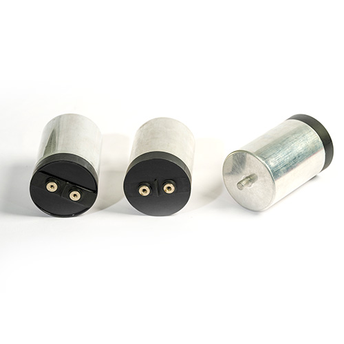
DC-Link Capacitors for New Energy Power Generation
Description
Round DC-Link capacitors are primarily used in new energy power generation systems. In wind power generation, these capacitors help mitigate voltage fluctuations and flicker issues in wind turbine systems. In photovoltaic (PV) systems, they absorb harmonics and voltage spikes generated during DC/AC conversion. DC-Link capacitors ensure the quality of power output from renewable energy sources, maintaining the stable operation of electrical equipment within the system. Improving power quality with DC-Link capacitors is crucial for advancing new energy power generation.
Features
Self-healing metallized film capacitors, dry-type, metal casing, resin-encapsulated, long lifespan, resistant to explosion and vibration, UL94-V0 flame retardant rating.
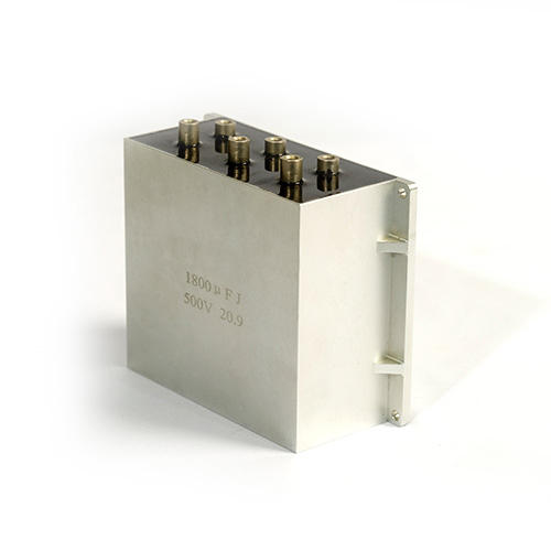
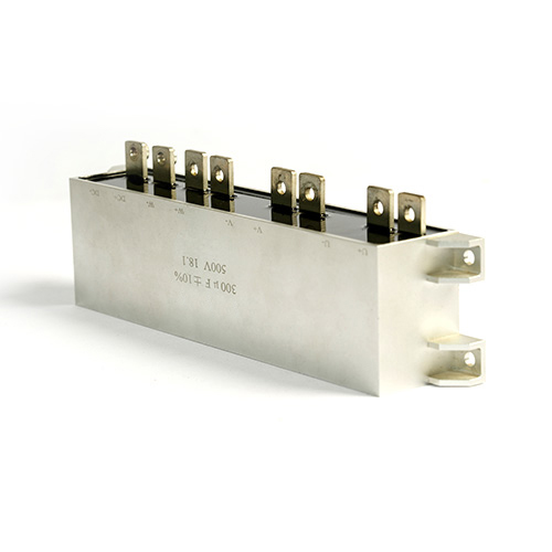
DC-Link Capacitors for Rail Traction Power Supply Systems
Description
Busbar DC-Link capacitors are mainly used in rail traction power supply systems and power/lighting systems. During locomotive operation, these capacitors filter various harmonics generated by converters and locomotive loads, enhancing the quality of converter output power. They also improve the power quality fed back to the grid via overhead lines, playing a vital role in the main and auxiliary power systems of both the grid and locomotives.
Features
Self-healing metallized film capacitors, dry-type, resin-encapsulated, long lifespan, resistant to explosion and vibration, UL94-V0 flame retardant rating.
DC-Link Capacitors for Flexible HVDC Transmission Projects
Description
Flexible DC-Link capacitors are critical components in flexible high-voltage direct current (HVDC) transmission projects, also known as DC-Link capacitors. They are installed in valve towers alongside IGBT converter devices to stabilize DC voltage in the circuit and absorb ripple currents, thereby protecting the IGBTs.
Features
Self-healing metallized film capacitors, dry-type, resin-encapsulated, long lifespan, resistant to explosion, UL94-V0 flame retardant rating.
Classification by Rated Voltage
DC-Link capacitors can also be classified based on their rated voltage, which determines the maximum voltage they can withstand before failure occurs. The rated voltage influences the design and structure of the capacitors
Low-Voltage Capacitors
Voltage Range
Typically less than 1 kV
Application
These capacitors are used in low-power applications that do not require high voltage
High-Voltage Capacitors
Voltage Range
Typically from 1 kV to several hundred kV
Application
High-voltage direct current support capacitors are used in high-energy power systems
Classification by Capacitance Value
The capacitance value plays a significant role in determining the energy storage capacity of the pulse capacitor.
Small-Capacitance Pulse Capacitors
Capacitance Range
From a few nanofarads (nF) to microfarads (μF).
Large-Capacitance Pulse Capacitors
Capacitance Range
From microfarads (μF) to several thousand microfarads (μF).
Parameters of DC-Link capacitor
When designing or selecting DC-Link capacitors, several key parameters determine their performance and suitability for specific applications. These parameters include capacitance, voltage, current and dissipation, etc. Below are details of the most important parameters for DC-Link capacitors.
Capacitance (C)
Definition
The capacitance of a capacitor represents its ability to store electrical charge, and it is measured in farads (F). Capacitance is a key factor in determining how much energy the capacitor can store.
Factors of capacitance size
- Plate area (A): the larger the area, the larger the capacitance.
- Plate spacing (d): the smaller the spacing, the greater the capacitance.
- Dielectric constant (ε): the higher the dielectric constant of the dielectric material, the higher the capacitance.
Thermal Stability (Temperature Range)
Definition
The temperature range of the capacitor indicates the environmental conditions in which the capacitor can operate without failure. It is typically expressed as a range, such as -40°C to +85°C.
Importance
In high-power applications, DC-Link capacitors generate a significant amount of heat during operation. Therefore, excellent thermal stability is crucial to prevent capacitor failure.
Rated DC Voltage(UNDC)
Description
The rated voltage is the continuous voltage that a capacitor can withstand without the risk of dielectric breakdown or failure.
Application
It is like the “upper voltage limit” that a capacitor can withstand when working. Exceeding this value may cause the capacitor damaged, such as breakdown, bulging or even explosion.
Key selection points
Leave a safety margin. In order to make capacitors more durable, it is best to choose a rated value higher than the circuit voltage. For example, if the circuit voltage is 1000V, capacitors with rated voltage of 1500V or 2000V can be selected.
Typical Range
The rated DC voltage of DC-Link Capacitor may range from 400V to 10 kV.
Withstand Voltage
Definition
The withstand voltage of a capacitor refers to the maximum voltage it can withstand across its terminals without breaking down or sustaining damage. This is typically tested by applying a high voltage (usually 1.5 times higher than the rated voltage) for a short duration (usually 60 seconds) —to verify the capacitor’s insulation and dielectric materials can handle transient overvoltages. This test is also known as the “dielectric withstand voltage” or “hi-pot (high potential) test.”
Caution
It is a short-term, high-voltage test (not continuous operation). It verifies the integrity and safety of insulation. Exceeding this voltage may cause dielectric breakdown, internal arcing or permanent failure.
Example
If a capacitor has a rated voltage of 100 V and a withstand voltage of 250 V for 2 seconds, it means it can safely handle up to 250 V for 2 seconds under test conditions but should not operate continuously above 100 V.
Equivalent Series Resistance (ESR)
Definition
ESR, which stands for Equivalent Series Resistance, is the internal resistance that affects the rate at which a capacitor discharges its energy. It represents the combined resistance of the internal components of the capacitor, including the dielectric, leads, and electrode connections. A lower ESR indicates better capacitor performance.
Impacts and effects
- Energy Loss: ESR causes capacitors to generate heat during the charging and discharging process, resulting in power loss. This loss is particularly noticeable in high-frequency or high-current applications and may lead to increase capacitor temperature, thereby affecting its performance and lifespan.
- Filtering effect: ESR affects the filtering performance of capacitors. In filter circuit, the ESR of the capacitor and the capacitance value jointly determine the size of the ripple voltage. Excessive ESR increase ripple voltage, reducing filtering efficiency.
- Voltage Stability: ESR causes transient voltage at the capacitor terminals during charging and discharging, affecting voltage stability. During sudden load changes, high ESR may cause excessive voltage fluctuations and even lead to circuit failures.
- Circuit Stability: In some circuits, such as oscillating circuits, changes in ESR may cause functional changes in the circuit, leading to circuit failure or even damage.
Maximum Peak Current Î
Definition
The Maximum Peak Current” of a capacitor refers to the highest instantaneous current that the capacitor can safely handle without degradation or damage. This specification is important because capacitors, especially those in power electronics applications, may encounter very high surge currents during charging or discharging. Manufacturers usually specify this value in datasheets based on testing conditions and capacitor type
Limiting factors
- Internal resistance (ESR – Equivalent Series Resistance)
- Heat dissipation limitation
- Dielectric strength and structure
Application relevance
Especially critical in circuits with high di/dt (rate of current change), such as switching power supplies, inverters, and pulse applications.
Caution
Exceeding the maximum peak current can cause:
- Excessive heating
- Breakdown of dielectric material
- Premature failure of the capacitor
Equivalent Serial Inductance (ESL)
Definition
Equivalent serial inductance (ESL) is a parameter used to simulate the parasitic inductance of components (usually capacitors or resistors) when represented in a circuit. It explains the parasitic inductance behavior exhibited by actual components due to their physical structure, such as leads or internal geometry.
Key points
- It is usually expressed as nanohenries (nH).
- Becomes significant at high frequencies, where inductive effects can impact circuit performance.
- Important in high-speed digital, RF, and power electronics applications.
Application relevance
Especially critical in circuits with high di/dt (rate of current change), such as switching power supplies, inverters, and pulse applications.
Caution
Exceeding the maximum peak current can cause:
- Excessive heating
- Breakdown of dielectric material
- Premature failure of the capacitor
Loss Tangent(100Hz)tanδ
Definition
The loss tangent (also known as the dissipation factor or tan δ) is a measure of the energy loss within the dielectric material of the capacitor.
Formula


What it Represents
The loss tangent (tanδ) quantifies how much energy is dissipated in the form of heat and how much is stored and returned by the capacitor. A lower tan δ means a more efficient capacitor (less energy loss), while a higher tan δ indicates greater energy dissipation.
Maximum Effective Current Ieff
Definition
The maximum effective current of a capacitor refers to the highest alternating current (AC) that the capacitor can handle without exceeding its temperature or performance limits. It is usually specified in the datasheet of the capacitor and depends on factors such as:
- Capacitor type (electrolytic, ceramic, film, etc.)
- Operating frequency
- Capacitance and rated voltage
- Internal resistance (equivalent series resistance or ESR)
Caution
If the current exceeds this maximum value, the capacitor may overheat, degrade, or fail. Therefore, in circuit design, it’s essential to select a capacitor with a maximum effective current rating higher than the expected current in the application.
Service Life
Definition
The service life of a capacitor refers to the expected operational lifetime before it experiences significant degradation or failure.
Factors of Reducing Life
- High ambient temperature
- Ripple current (excessive AC component)
- Electrical overstress (voltage surges)
- Mechanical stress or vibration
Degradation signs of capacitors
- Increased ESR (Equivalent Series Resistance)
- Reduced capacitance
- Increased loss
- Leakage or bulging in capacitors
Structure of DC-Link Capacitors
The structure of a DC-Link capacitor typically consists of the following main components:
Dielectric Material
Provides the electrical insulation between the electrodes, allowing for energy storage.
Conductive Plates
These form the electrodes that store charge when voltage is applied.
Winding or Stacked Configuration
Maximizes the surface area for the electrodes, hereby achieving higher capacitance.
Enclosure
Made of materials such as aluminum or steel, providing mechanical protection and heat dissipation.
Terminals
Allow for electrical connection to the external circuit.
Insulation and Safety Features
Ensure safe operation by protecting the capacitor from electrical breakdown and thermal damage.
Dielectric Material
Description
The dielectric is the insulating material that separates the two conductive plates of the capacitor. The dielectric material is crucial in determining the voltage rating and capacitance of the capacitor.
Material Selection
Polypropylene (PP): Commonly used in high-energy capacitors due to its low ESR (Equivalent Series Resistance) and excellent thermal stability.
Polyester (PET): Due to its mechanical strength and good dielectric properties, it is used in certain applications.
Conductive Plates (Electrodes)
Material
Electrodes are typically made of aluminum, copper, or silver due to their excellent conductivity. For high-voltage applications, a thin layer of silver or gold can be coated on the plate to reduce oxidation and enhance conductivity.
Structure
Electrodes are usually in the form of flat plates or cylindrical sheets. The design of the electrode plate affects the overall capacitance and the energy density of the capacitor.
Electrode Geometry
In many DC-Link capacitors, the electrode plates are wound or stacked with the dielectric material in between. This design maximizes the surface area and achieves higher capacitance and rated voltage within a compact space.
Winding or Stacking Configuration
Wound Capacitors
In most DC-Link capacitors, the dielectric film and electrodes are wound into a cylindrical shape. The film is typically rolled into tight layers, and metal electrodes are applied between the layers to create the necessary capacitance.
Wound design helps achieve a large surface area and increases the energy storage capacity without increasing the size of the capacitor excessively.
This structure is more common in applications that require large capacitors and the ability to with stand high currents.
Stacked Capacitors
In some designs, multiple layers of dielectric material and electrodes are stacked on top of each other to achieve the desired capacitance and rated voltage. This configuration is more common in larger or high-voltage capacitors, such as those used in radar systems or energy storage systems.
Enclosure
Material
The case of a capacitor is typically made from high-strength metals such as aluminum or stainless steel, and sometimes from plastic for lighter applications.
Purpose
The case serves as an enclosure to protect the internal components from environmental damage, mechanical stress, and electrical short circuits. It also provides structural integrity and aids in heat dissipation.
Heat Dissipation
In DC-Link capacitors, thermal management is very importance. The capacitor body typically includes heat-dissipating metals or air gaps to ensure effective heat dissipation during rapid charge/discharge cycles.
Terminals
Purpose
The terminals are used to connect the capacitor to the external circuit and allow for charging and discharging.
Materials
Typically made of highly conductive metals such as brass, copper, or aluminum.
Design Consideration
The design of the terminals is critical for DC-Link capacitors, as they must handle high currents during discharge without causing excessive heating or resistance.
Insulating Layers (Insulation)
Purpose
In addition to dielectric materials, high-energy pulse capacitors often employ an additional insulation layer between the body and electrodes to ensure safety and withstand high voltage.
Materials
In addition to dielectric materials, DC-Link capacitors often employ an additional insulation layer between the body and electrodes to ensure safety and withstand high voltage.
Epoxy Resin: A common material used for potting capacitors, providing additional insulation and protection.
Ceramic: In certain cases, ceramic insulation is utilized for high-voltage designs.
Paper and Oil: Older designs used oil-impregnated paper, which provides both insulation and cooling
The structure of DC-Link capacitors is designed to:
1. Smooth and filter the output voltage in inverter circuits;
2. Absorb high-amplitude ripple currents drawn by the inverter from the DC-Link, preventing them from generating high-amplitude ripple voltages across the DC-Link impedance;
3. Protect IGBTs from voltage overshoots and transient over voltages originating from the DC-Link.
These capacitors are commonly used in charging stations, renewable energy power generation, electric locomotives, and high-voltage flexible DC transmission systems.
How to Design DC-Link Capacitor
Designing a DC-Link capacitor requires careful consideration of multiple parameters to ensure optimal performance, safety, and reliability. These capacitors are commonly used in high-power power conversion systems, such as rectifiers, inverters, and AC/DC switching applications. Below is a step-by-step guide on how to design a DC-Link capacitor:
Determine the Energy Requirements
Capacitance and Voltage
The first step in designing a DC-Link capacitor is to understand the energy storage needs. The stored energy (E) in a capacitor is given by the formula: E=1/2CV2
E is the energy stored in joules (J); C is the capacitance in farads (F); V is the applied voltage in volts (V)
Choose the Dielectric Material
Material
The dielectric material is critical for determining the voltage rating, energy density, and discharge characteristics of the capacitor.
Polypropylene (PP): Commonly used in pulse capacitors due to its low ESR, high insulation resistance, and good thermal stability.
Ceramics: Can be used for very high-voltage capacitors, but they are more brittle.
Polyester (PET): Sometimes used, offering moderate dielectric strength.
Oiled paper: Often used in older designs, suitable for high-energy storage but is less common in modern systems.
Dielectric Breakdown Strength
The dielectric material must be able to withstand the voltage without breaking down. This is known as the dielectric strength and is usually expressed in V/m or kV/mm. A high dielectric strength allows for higher voltage ratings.
Selection of Thickness
The thickness of a dielectric material is inversely proportional to its dielectric strength. Thicker dielectrics can handle higher voltages but will reduce the energy density of the capacitor. Choose the thickness based on the required voltage and energy.
Design the Electrodes (Conductive Plates)
Electrodes
The electrodes are the conductive materials (typically made of aluminum, copper, or silver) that store and release charge when the capacitor is charged and discharged. The geometry of the electrodes affects the capacitor’s capacitance and energy storage.
Surface Area: The larger the surface area of the electrodes, the higher the capacitance. Electrodes can be designed as flat plates, cylindrical wraps, or stacked layers to maximize surface area within the capacitor’s dimensions.
Thickness of Electrodes: The thickness of the electrodes must be chosen to balance between resistance and current-carrying capacity. Thicker electrodes can handle higher currents but add to the overall size and weight of the capacitor.
Shape and Configuration: DC-Link capacitors often use wound or stacked configurations, where layers of electrodes and dielectric materials are rolled or stacked to maximize capacitance without excessively increasing the physical size.
Determine the Capacitance (C)
Capacitance Calculation
The capacitance depends on the dielectric constant (ε) of the chosen dielectric material, the surface area of the electrodes (A), and the distance between the electrodes (d).
For a parallel-plate capacitor, the capacitance is given by:

In the case of wound or stacked capacitors, the effective area (A) is increased by the number of layers, and the thickness of the dielectric (d) is determined by the film thickness used.
Relationship between Capacitance and Energy
Once you’ve chosen the dielectric material, electrode configuration, and voltage, you can calculate the required capacitance based on the energy storage requirement (using the formula from earlier).
Optimize Pulse Discharge Characteristics of the DC-Link Capacitor
ESR (Equivalent Series Resistance)
For DC-Link capacitors, ESR is a key parameter because it affects the speed and efficiency of the discharge. A low ESR allows the capacitor to release energy rapidly with minimal resistance. It is critical for high-speed, high-current applications.
Material Selection: Both the electrodes and dielectric use materials with low resistance. Aluminum electrodes and polypropylene dielectric offer low ESR and high discharge efficiency.
Current Handling Capability: The design of DC-Link capacitors must be able to withstand very high currents during rapid discharge. Ensure that the electrode design and dielectric material can handle the high ripple current. The ripple current of capacitors used in high-power applications may reach several hundred amperes.
Mechanical and Thermal Considerations
Mechanical Structure
The physical casing or housing of the capacitor must protect the internal components from mechanical damage and be capable of withstanding the pressure generated during rapid discharge. Utilize robust materials such as aluminum or stainless steel to construct the casing.
Thermal Management
DC-Link capacitors generate significant heat during rapid discharge. It is essential to account for thermal expansion and ensure that the capacitor can effectively dissipate heat to prevent overheating and dielectric failure.
Cooling System: For very high-power systems, consider using liquid cooling or attaching a heat sink to the capacitor for active cooling.
Thermal Fuse: Implement a thermal protection circuit to disconnect the capacitor if it exceeds safe temperature limits.
Determine Capacitance Configuration
Series and Parallel Configurations
Depending on the required voltage and capacitance, you may need to combine multiple capacitors in series or parallel:
Series connection: Increases the voltage rating while keeping the capacitance constant. The total capacitance is reduced, but the voltage rating is increased.
Parallel connection: Increases the total capacitance while keeping the voltage rating the same. The total energy storage increases, but the voltage rating remains constant.
Balancing Voltage Across Capacitors: If connecting capacitors in series, use voltage-balancing resistors to ensure that the voltage is evenly distributed across all capacitors.
Safety and Reliability Features
Pressure Relief and Venting
Capacitors, especially large ones, can accumulate gas or pressure during rapid discharge. Design the capacitor with venting systems or pressure relief valves to avoid catastrophic failures.
Overvoltage and Overcurrent Protection: Include safety features such as voltage clamping devices or current-limiting resistors to protect the capacitor and the circuit from overvoltage or overcurrent conditions.
Insulation: Ensure that the capacitor is fully insulated from external circuits and its environment to prevent shorts and leakage. Use high-voltage insulation materials for terminal connections and enclosures.
Test and Prototype
After completing the design, it’s crucial to prototype the capacitor and test its performance under actual operating conditions. This involves:
Testing the voltage rating to ensure the dielectric material does not break down.
Verifying the energy storage and discharge characteristics using appropriate pulse circuits.
Testing the thermal response to ensure the capacitor can handle the heat generated during discharge.
Precautions for Using DC-Link Capacitors
The safe and effective use of DC-Link capacitors is crucial, as they have the potential to store and release a significant amount of energy in a very short time. If not handled properly, they can pose substantial risks, including electric shock, fire, and even mechanical failure due to pressure buildup. Below are some important precautions to consider when using high-energy pulse capacitors
Proper Voltage Rating Compliance
Precaution
Always ensure that the voltage rating of the capacitor exceeds the maximum voltage that will be applied during charging. Overvoltage can cause dielectric breakdown, resulting in failure or catastrophic discharge.
Solution
Never apply voltages higher than the rated voltage of the capacitor. If multiple capacitors are connected in series or parallel, ensure the voltage division is correctly managed across all capacitors.
Discharge Safety
Precaution
Capacitors can store very large amounts of energy and discharge it rapidly. An unintended discharge can result in electric shock, arc flash, or fire.
Solution
Always discharge capacitors safely before handling them. Use a resistor or discharge tool to ensure the capacitor is fully discharged. For high-voltage capacitors, ensure the discharge is done through a high-voltage resistor to safely dissipate the stored energy.
Handling and Installation
Precaution
Improper installation or handling can damage the capacitor and lead to dangerous conditions like short circuits or mechanical failure.
Solution
- Mount capacitors securelyto prevent physical damage.
- Use appropriate insulationand avoid contact with conductive materials to prevent shorts.
- Ensure that any capacitor leads or terminals are properly insulated to prevent accidental contact.
Avoiding Short Circuits
Precaution
A short circuit can cause a massive current surge through the capacitor, potentially damaging the capacitor or other components in the circuit. It can also result in dangerous overheating and even explosion in extreme cases.
Solution
Always check for proper insulation and ensure that no wires or conductive parts are in contact with the capacitor terminals when not intended. Use fuse protection and current-limiting devices to prevent catastrophic failures.
Avoiding Reverse Polarity
Precaution
Some types of capacitors, particularly electrolytic capacitors, are sensitive to reverse polarity and can be damaged or even explode if connected incorrectly.
Solution
Double-check the polarity before connecting the capacitor in the circuit. Ensure correct orientation of the capacitor in the circuit to avoid reverse voltage application.
Proper Circuit Design
Precaution
Incorrect circuit design, including improper resistor values for discharge or charging circuits, can lead to inefficient operation or failure of the capacitor.
Solution
Design the DC-Link capacitor circuits carefully, ensuring that components like resistors and inductors are properly rated for the capacitor’s energy and voltage levels. Consider voltage regulation circuits and ensure that the capacitor is not subject to sudden voltage spikes.
Avoid Physical Impact and Vibration
Precaution
DC-Link capacitors are sensitive to mechanical shock or vibration, which can cause internal damage, breakage of connections, or dielectric rupture.
Solution
Ensure that capacitors are mounted securely in place to avoid vibration or shock during operation. Use shock-absorbing mounts or gaskets in systems prone to mechanical stress.
Pre-Charge the Capacitor Gradually
Precaution
Rapid charging of capacitors can lead to overheating, dielectric breakdown, or excessive stress on internal components.
Solution
Gradually charge the capacitor using a current-limiting resistor to ensure the voltage increases at a safe rate, especially for large capacitors.
Periodic Inspection and Maintenance
Precaution
Over time, capacitors may degrade, especially if used in high-energy systems with frequent charge / discharge cycles.
Solution
Regularly inspect capacitors for signs of wear, such as: Deterioration of the dielectric, Cracks or bulges in the casing, Corrosion on terminals, Replace capacitors if any damage or degradation is observed.
Avoid Long-Term Storage Under Full Charge
Precaution
Storing DC-Link capacitors in a charged state for prolonged periods can cause dielectric degradation or increase the risk of electrostatic discharge.
Solution
If not in use, discharge capacitors to a safe level (usually a small voltage) and store them in a discharged state.
Environmental Conditions
Precaution
DC-Link capacitors are sensitive to moisture, extreme temperatures, and corrosive environments.
Solution
- Ensure capacitors are sealed against moisture or environmental contaminants.
- Keep capacitors away from extremely high temperatures or direct sunlight.
- Store and operate capacitors in dry, cool, and well-ventilated areas.
Use of Safety Equipment
Precaution
Capacitors, particularly high-voltage ones, can pose a risk of electrical shock to personnel.
Solution
Always use appropriate personal protective equipment (PPE) when working with high-energy capacitors:
- Insulated gloves for electrical protection.
- Face shields or safety goggles to protect against arc flashes or accidental discharges.
- Non-conductive tools to avoid short circuits when adjusting or replacing capacitors.
Temperature Control and Thermal Management
Precaution
During operation, DC-Link capacitors can generate substantial heat. High temperatures can lead to dielectric breakdown, reduced performance, and failure.
Solution
- Ensure proper cooling mechanisms are in place, especially in systems that require repeated pulsing (e.g., using heat sinks, cooling fans, or liquid cooling for high-power applications).
- Monitor the temperature of the capacitor using temperature sensors or thermal cutoffs to avoid overheating.
- Ensure that the capacitor’s temperature stays within the manufacturer’s specified limitsduring use.
Pressure Relief and Ventilation
Precaution
DC-Link capacitors can generate gases or high internal pressure during long term operation, especially if they overheat. If these gases are not vented, the capacitor can burst or explode.
Solution
- Ensure the capacitor is installed with adequate ventilation and pressure relief to prevent pressure build-up.
- Use pressure-relief valves or venting systems in high-energy systems to allow gases or heat to escape.
- Be aware of safety venting zones around the capacitor in case of sudden failure.

