
As a professional manufacturer and supplier of feedthrough filter, Shieldtechnic is committed to providing you with higher performance feedthrough filter. Whether you are looking for a traditional standard filter or a customized design based on the specific needs of your project, Shieldtechnic can meet your needs.
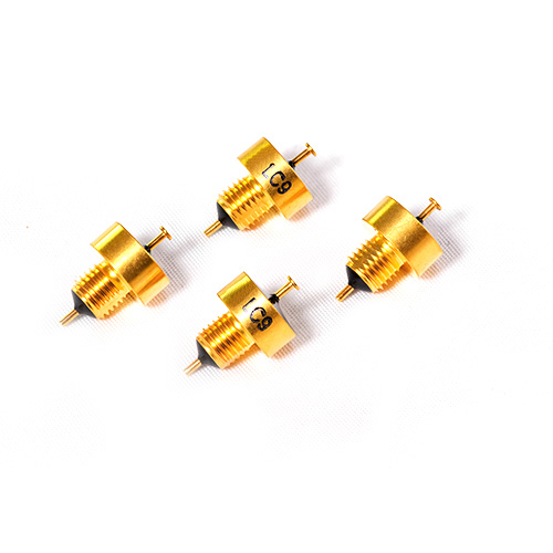
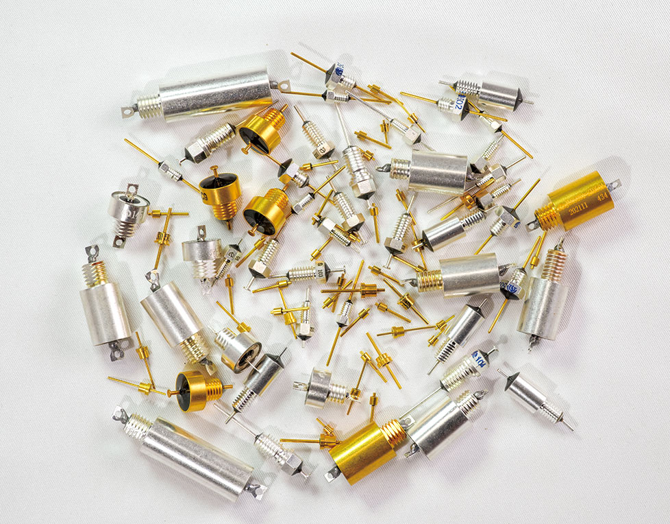
We have extensive experience in customizing feedthrough filters, some of which we have produced in recent years are listed below.


| Nomal Parameter and Range | ||
| Parameter | Typical Range | |
| Circuits | C/π/T/L | |
| Capacitance | 0pF~3μF | |
| Tolerance | ±20%、-20%~+50%、-20%~+80%、0~+100% | |
| Voltage – Rated | 50VDC、63VDC、100VDC、200VDC | |
| Current | 2A、5A、10A、20A | |
| Operating Temperature | -40℃~+85℃、-55℃~+85℃、-55℃~+100℃、-55℃~+125℃ | |
| Chip style | Multi-Layer Plate / Single Layer Plate/Porcelain tube | |
| Mounting Methods | Surface-mount | |
| Welded | M2.5-M10 | |
| Solder-in | Ø2–Ø10 | |
| The feedthrough filter can be customized, including parameter normal range and parameter exceeding normal range. | ||
Are you still struggling to find the right feedthrough filter? Are you still suffering from the headache of complicated customization process? Shieldtechnic has been focusing on feedthrough filters for 25 years, and we know your pain points well! Now, just tell us your requirements (your application scenario, the frequency range of signals you need to filter, your special requirements on filter size, interface, etc.), and we will provide you with a solution and quotation within 24 hours of receiving the message.
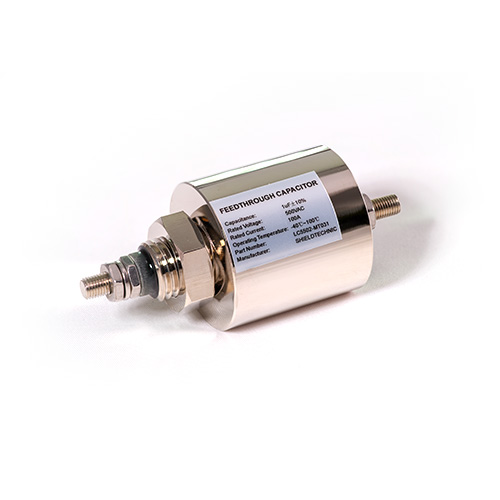
A Feedthrough Filter is an electronic component specifically designed to suppress high-frequency noise and interference signals. It is typically mounted on a metal panel or shielded enclosure and is used to block electromagnetic interference (EMI) and radio frequency interference (RFI) in signal line or power line.
The electromagnetic interference (EMI) and radio frequency interference (RFI) enter another side in signal line or power line when the lines across the metal panel or shielded enclosure if there is no filtering component involved.
A feedthrough filter can release interference (EMI) and radio frequency interference (RFI) to ground through metal panel or shielded enclosures. It is necessary mainly to keep electronic systems clean, stable, and interference-free — especially when signals or power need to pass in and out of metal panel or shielded enclosures.
Feedthrough filters are critical in military electronics, aircraft, and spacecraft for suppressing electromagnetic interference (EMI) and ensuring reliable communication, navigation, and control systems. They must withstand extreme environmental conditions such as high vibration, temperature fluctuations, and radiation.
In base stations, radar systems, and microwave communication equipment, feedthrough filters prevent EMI from disrupting signal integrity and communication quality. High-frequency performance (e.g., GHz range) is essential to meet stringent EMC standards.
Equipment like MRI machines, CT scanners, and life-support systems rely on feedthrough filters to protect against EMI, ensuring patient safety and accurate diagnostics. These filters must meet medical safety certifications with low leakage currents and high isolation.
Feedthrough filters are used in PLCs, industrial robots, and sensor networks to mitigate EMI from variable-frequency drives (VFDs) and motors, ensuring stable operation in harsh industrial environments.
In electric vehicles (EVs) and hybrid electric vehicles (HEVs), feedthrough filters in battery management systems (BMS) and motor controllers suppress high-frequency noise from switching power supplies, meeting automotive reliability standards.
Feedthrough filters in photovoltaic inverters, wind turbine converters, and power electronic transformers reduce harmonics and EMI generated by power electronics, ensuring grid compliance and system efficiency.
In high-speed trains and metros, feedthrough filters protect signaling and traction systems from EMI, ensuring reliable train control and communication in challenging environments.
Feedthrough filters in spectrum analyzers, oscilloscopes, and high-precision measurement equipment shield sensitive circuits from external EMI, maintaining measurement accuracy.
In smartphones, tablets, and laptops, feedthrough filters in USB ports and power adapters suppress EMI and radiation, meeting EMC compliance for consumer safety and performance.
Feedthrough filters in network cameras, access control systems, and alarm systems prevent EMI from disrupting video transmission and device stability, even in harsh outdoor conditions.
Laboratory equipment and test instruments use feedthrough filters to isolate noise sources, ensuring accurate test results and reliable operation.
In smart homes, wearables, and wireless sensor networks, feedthrough filters minimize EMI from wireless communication modules, supporting miniaturization and low-power designs.
Consists of bushing-type condenser, used to connect high impedance source and high impedance load and to control high frequency signals.

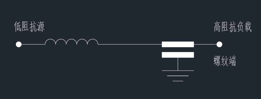
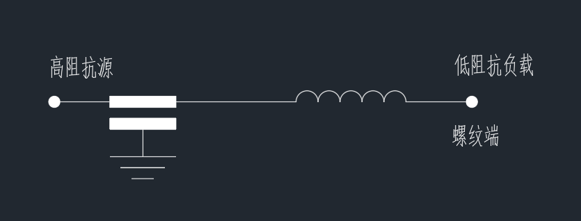
Includes an inductor and a capacitor. It can provide high input impedance or low input impedance according to circuit installment. L1 circuit is applicable when there is high impedance load and low impedance source; L2 circuit is applicable when there is low impedance load and high impedance source.
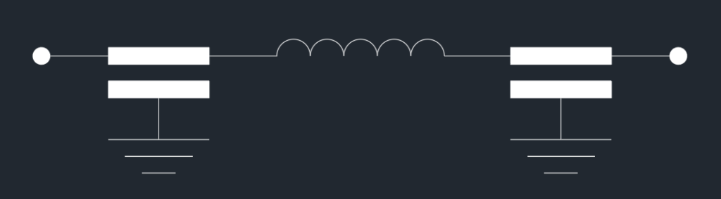
Includes two capacitors and one inductor, both input and output ports are of low impedance. Compared with L filter, it contains more components and thus has better insertion loss. When used in a switching circuit, it is likely to have a ringing Effect.
Is a π filter with a transient suppressor added to its inputport. It has better performance in suppressing high frequency and prevents spike.
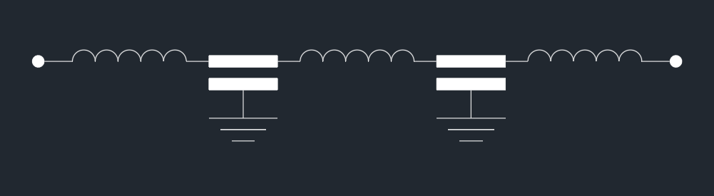
Includes one capacitor and two inductors with both ports being Hag impedance. Its insertion loss is similar to π filter, but it is not venerable to ringing effect and can be applied in switching circuit.

A high-performance filter designed for a circuit with low impedance Source and low impedance load. It can also be applied where high insertion loss is required. It will be helpful to pass American Military Standard MIL-STD-461D.
Attenuation of the signal passing through the filter at a specific frequency.

Measured in dB; higher values indicate better filtering.
Critical for compliance with EMI standards (e.g., CISPR, FCC).
Frequency where the filter’s response transitions from passband to stopband.
A low-pass filter with fₒ = 100 MHz allows frequencies below 100 MHz to pass with minimal attenuation.
Electrical resistance to signal flow at the filter’s input/output.
Source Impedance (Zₛ): Impedance of the source driving the filter.
Load Impedance (Zₗ): Impedance of the device connected to the filter.
Matched Impedance: Zₛ = Zₗ = 50 Ω (common in RF systems).
Frequency where the filter’s inductive and capacitive reactances cancel, leading to minimal impedance.
LC filters exhibit a resonant peak at
Maximum continuous current the filter can handle without overheating.
A filter rated for 1 A may degrade if subjected to 2 A continuously.
The voltage that feedthrough filter can work normally and continuously.
A 250 VAC filter is suitable for mains-powered applications.
Voltage at which dielectric failure occurs.
Ensures safety and reliability under transient surges.
Resistance between the filter’s conductive elements and its housing.
High R_ins (e.g., >1 GΩ) minimizes leakage currents in medical devices.
Current flowing through the filter’s insulation under applied voltage.
Medical filters often require leakage < 10 μA at 250 VAC.

1. Panel Mounting: The filter is installed directly onto a metal panel with low ground impedance. This method leverages the panel as both a grounding point and a shield to isolate the filter’s input and output.
2. PCB Mounting: For circuit board applications, the filter can be surface-mounted or through-hole mounted, with connections to the ground plane for optimal performance.
3. Isolation Board Mounting: In scenarios where panel mounting is infeasible, the filter can be mounted on a metal isolation board to provide high-frequency filtering capabilities.
1. Welding Installation:
Advantages: Space-saving and reliable filtering performance.
Considerations: Control welding time and temperature to prevent damage to the filter’s internal components, as the panel’s thermal capacity is much higher than the filter’s.
2. Screw Installation:
Advantages: Simple and easy to implement.
Considerations: Use a torque-controlled tool to avoid over-tightening, which could damage the filter. Serrated washers are recommended to maintain good contact.

The filter’s casing must be securely connected to the panel’s ground to provide a low-impedance path for interference signals.
Input and output leads should not exit from the same side of the filter to prevent coupling between them. If necessary, a shielding layer can be added between the leads.
Internal connections within the filter should be as short as possible to minimize interference coupling, especially for unshielded leads exposed to strong electromagnetic fields.
When bending or trimming leads, excessive force should be avoided to prevent damage to the filter’s internal components.
During welding, avoid sudden thermal shocks that could cause internal ceramic capacitors to crack. Use a low-temperature soldering process and allow the filter to cool naturally.
For resin-sealed filters, avoid immediate cleaning with cold liquids after welding to prevent damage to internal components.
For example, an M2.5 thread may require a torque of 0.15 N·m, while an M5 thread may require 0.5 N·m. These values ensure proper installation without damaging the filter.
The filter’s operating environment should be considered during installation to ensure it meets the required specifications for temperature, humidity, and vibration.
In high-noise environments, the filter may require additional shielding, such as a metal enclosure or a coaxial cable, to further isolate it from external interference.
The filter’s design should match the impedance characteristics of the connected system to ensure optimal performance.
Use tools with torque settings (e.g., torque wrenches) to ensure proper installation and avoid damage to the filter.

Shieldtechnic produces premium capacitors, filters, and injection molding parts. We focus on high-quality, reliable components for international markets.
Sign up for the Shieldtechnic newsletter with your email and instantly receive our E-CATALOG.
WhatsApp us