Skip to content
The Features of Feedthrough Filter
The feedthrough filter, a low-pass EMI passive component, has an effective control over conducted interference signals and radiation interference signals in transmission line and power line.
The feedthrough filter can be classified into low-pass filter, high-pass filter, VHF (very high frequency) filter and microwave filter in terms of frequency band. In accordance with circuit structure, is can be classified into C filter, L filter, π filter, T filter, double-L filter, double-π filter and double-T filter and so on. In terms of installment, the feedthrough filter can be classified into threaded fastener filter and soldering filter and it can be classified into ceramic tube filter, ceramic chip filter and organic film filter and so on.
Feedthrough Filter Selection Guide
To choose a suitable feedthrough filter, the configuration and size of the filter should be selected in accordance with space and installment method and its electric parameter should be chosen according to voltage and current. With the help of following suggestions, you will find a suitable type.
1. Circuit configuration
On the principle of impedance mismatching, the larger is the mismaching between filter impedance and port impedance of each sides, the more effective it would be to attenuate the EMI. Consequently, the high impedance of the circuit should be connected to the low impedance of the filter, and the low impedance of the circuit should be connected to the high impedance of the filter, as shown in Diagram 1. Furthermore, the circuit configuration of the filter should be chosen in accordance with filter requirements.
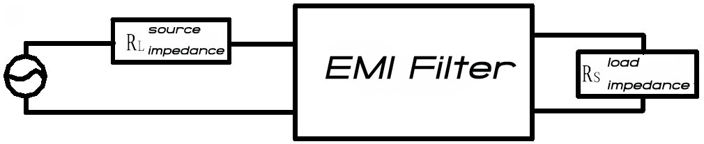
Diagram1
2. The Insertion Loss Parameter Of Feedthrough Filter
The main parameter of filter is insertion loss which reflects filter’s strength to control interference signals. Insertion loss of filter should be chosen in accordance with the frequency of interference signals and attenuation degree and frequency because each EMI filter has its own attenuation and frequency curve. It is worth mentioning that insertion loss given by manufacturers are data gathered is 50Ω system with no-load, while in real circuit the input /output impedance is not precise 50Ω. Therefore, the insertion loss value of a filter in circuit is usually different from the one marked on the product. To measure the performance and filter, the methods of approximate measurement and on-line measurement are applied so get a closer to real situation.
Different circuits of feedthrough filter are shown in the right diagrams.
C Filter
Consists of bushing-type condenser, used to connect high impedance source and high impedance load and to control high frequency signals.

LC Filter
Includes an inductor and a capacitor. It can provide high input impedance or low input impedance according to circuit installment. L1 circuit is applicable when there is high impedance load and low impedance source; L2 circuit is applicable when there is low impedance load and high impedance source.
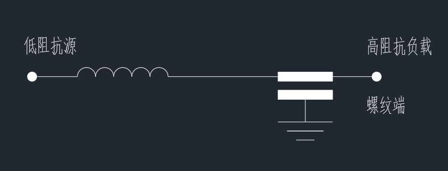
L1
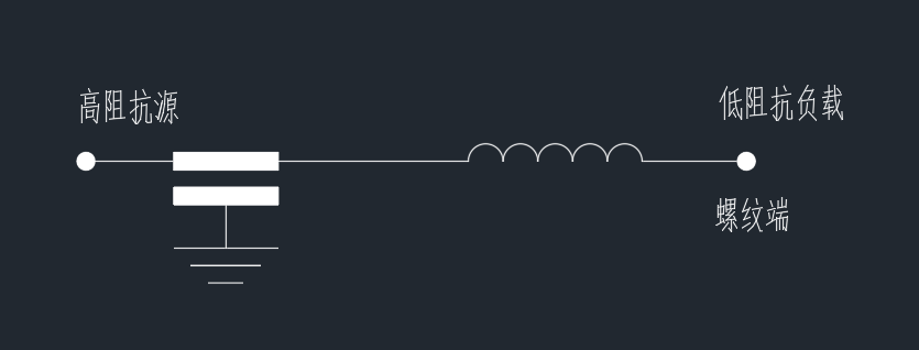
L2
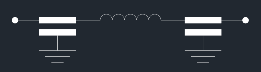
Pi Filter
Includes two capacitors and one inductor, both input and output ports are of low impedance. Compared with L filter, it contains more components and thushas better insertion loss. When used in a switching circuit, it is likely to have a ringing effect.
Pi Filter with Transient Suppressor
Is a π filter with a transient suppressor added to its input terminal. It has better performance in suppressing high frequency and prevents spike.
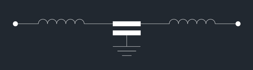
T Filter
Includes one capacitor and two inductors with both ports being hag impedance. Its insertion loss is similar to π filter, but it is not venerable to ringing effect and can be applied in switching circuit.
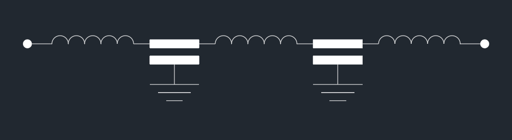
Multilayer Filter (Double T Filter)
Is a high performance filter designed for a circuit with low impedance Source and low impedance load. It can also be applied where high insertion loss is required. It will be helpful to pass American Military Standard MIL-STD-461D.
3. Cutoff Frequency of Feedthrough Filter
Cutoff frequency is an insertion loss at the point of 3 db frequency. Filter will enter a stop band when the frequency surpasses cutoff frequency and EMI signals will undergo a considerable attenuation. Therefore, filter cutoff frequency should be chosen carefully to guarantee the control of unwanted frequency signals and the passage of wanted signals. A signal should be filtered at a frequency ten times higher than its operation frequency. For instance, in a 5MHZ noise data circuit, the filter cutoff frequency should approximately be 50 MHZ. (The data provided here is just for reference).
Generally speaking, the size and the price of an filter is in reverse proportion to its cutoff frequency. Remember not to choose filters with a cutoff frequency that is too low, otherwise you may run the risk of filtering wanted electric signals.
4.Working Voltage of Feedthrough Filter
Is a voltage which a filter can sustain when it is working in the range of working temperature. In addition, alternating current filter should not be replaced by direct current filter, or vice verse, especially under the occasion of alternating current in which the usage of a direct current filter will become ineffective or even damaged.
5.Working Current of Feedthrough Filter
Is a current which a filter can perform normally in the range of operating temperature during operating hours. Working current is in proportion to lead diameter.
The Relationship between Feedthrough Filter Lead Diameter and Rated Working Current
Rated Current(A) | Diameter(mm) | Rated Current(A) | Diameter(mm) |
≤3 | 0.5 | >41~55 | 2.5 |
>3~5 | 0.6 | >55~73 | 3.2 |
>5~11 | 0.8 | >73~101 | 4.1 |
>11~16 | 1.0 | >101~135 | 5.1 |
>16~1.6 | 1.2 | >135~181 | 6.5 |
>22~32 | 1.6 | >181~211 | 7.4 |
>32~41 | 2.0 |
|
|
Notes: the above specified relationship between working current and lead diameter is just for references, and working current should be modified in accordance with lead material, working temperature and so on. | |||
It is worth mentioning that filter with wire wound inductor should take into consideration the quick saturation of magnetic material and the minuteness of the wire which consequently makes the filter sustain relatively low current.
6.Temperature Range of Feedthrough Filter
Refers to the temperature under which the electric performance of a filter is guaranteed. According to related standards, working temperature range are usually as follows: -25℃~+85℃, -40℃~+85℃, -55℃~+85℃, -55℃~+125℃. The inner of parts of Feedthrough Filter includes a ceramic medium capacitor whose features determine filter working temperature. Furthermore, the working temperature is related to temperature coefficient, that is, the change rate of ceramic medium capacitance changing with temperature. Feedthrough filter in our company generally adopt ceramic chip capacitor or ceramic tube capacitor . Temperature coefficients and property of common ceramic mediums are listed in Diagram 2:
Temperature Property and Coefficients of Common Ceramic Dielectric
Ceramic Dielectric Chip Capacitor | Ceramic Dielectric Tube Capacitor | ||||
Materials | Property(℃) | Coefficients * | Materials | Property(℃) | Coefficients * |
CH | -55~+125 | (0±60)ppm/℃ | U | -55~+125 | ±1% |
SL | -55~+85 | (+140~-1000)ppm/℃ | SL | -55~+125 | (350~1000)ppm/℃ |
X7R | -55~+125 | ±15% | 2B4 | -25~+85 | ±10% |
2E2 | -55℃~+85 | +20%~-55% | X7R | -55~+125 | ±15% |
2E3 | -40℃~+85 | +20%~-55% | 2E2 | -55~+85 | -56%~+22% |
2F2 | -55℃~+85 | +30%~-80% | Z5U | +10~+85 | +22%~+56% |
2C1 | -55℃~+125 | +20%~-20% | 2F4 | -25~+85 | -80%~+30% |
Notes: Temperature coefficients mentioned in the diagram are measured under no electric voltage. | |||||
Instructions To The Usage Of a Feedthrough Filter
1.Installment Notes
Since the installment method and craft will directly affect the performance of the filter, the following instructions should be followed when a filter is installed:
Firstly, an appropriate installment position should be chosen which is usually at the entrance to equipment or a screen;
Secondly, filter should be screened with its shell connected with filter ground line. The filter shell should be well connected with the equipment metal shell if it has one, the closer to the equipment shell grounding point, the better.
Thirdly, the inner connection of the filter should be short in case of coupling interference and unwanted exposition of strong electromagnetic field.
Fourthly, as regards thread fastened bushing-type condenser, it is recommended to use tools with torque scale to install. Requirements are as shown in Diagram 3:
Recommended Installment Torque
Diameter(mm) | Max(N·m) | Diameter(mm) | Max (N·m) |
M2.5 | 0.15 | M5 | 0.5 |
M3 | 0.2 | M6 | 0.6 |
M3.5 | 0.25 | M8 | 0.8 |
M4 | 0.3 | M10 | 1.0 |
Fifthly, contact resistance should be as small as possible to guarantee the bypass effect of the filter capacitor. To reduce contact resistance and to get a reliable connection, it is better to insert an inner gear, an outer gear ring and a mat between filter and isolation board.
Sixthly, to avoid the coupling of outer leads of the filter, it is required that input lead and output lead be drawn from different sides and an isolation screen should be inserted between these two groups of leads when necessary.
Seventhly, a soldering filter can be welded by means of ironing or hot air recirculation. When ironing soldering is adopted, the product should preheated under 150 Celsius degrees and ironing power should be under 35 w, with temperature no higher than 260 Celsius degrees. When temperature reaches that maximum, the soldering time should be no longer than 5s. When hot air recirculation soldering is adopted, the temperature should be changed according to the following curve:

2. With lead running through Feedthrough filter, ceramic capacitors, organic film capacitors and inductor, are vulnerable to thermal shocks, fierce mechanic force or sudden voltage rise. In consequence, force should not be overused to bend the lead. Moreover, relatively thick lead should not be bent or cut. Specifications should be explained directly to the manufacturer when necessary.
2. The filter should be connected to the ground wire of its base, that is, the filter shell should be grounded so as to eliminate interfering signals, by means of fastening the threaded shell, fastening the nut or by soldering.
3. Soldering time should be as short as possible in case that the ceramic capacitor might be damaged because of the thermal shocks. During the process of soldering, rosin flux should be used and the air should be cooled naturally in case that thermal shocks might cause an internal stress and thus impose an electric deterioration on the product.
4. Special tools such as torque scales, instead of pinchers, should be adopted to install the base of hexagon feedthrough filter.
5. Soak cleaning is not applicable to encapsulated feedthrough filter after soldering and the soldering point should not be washed by cool liquid immediately, or else the capacitor in the filter might be damaged. Measurement and adjustment should not be carried out until the filter is cold, cleaned and dried.